

LabVIEW block diagram

LabVIEW Front Panel

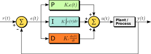
Block diagram of PID controller
The PID controller calculation (algorithm) involves three separate constant parameters, and is accordingly sometimes called three-term control: the proportional, the integral and derivative values, denoted P, I, and D. Heuristically, these values can be interpreted in terms of time: P depends on the present error, I on the accumulation of past errors, and D is a prediction of future errors, based on current rate of change. The weighted sum of these three actions is used to adjust the process via a control element such as the position of a control valve, or the power supplied to a heating element.

Simulate signal block is use to convert analog signal into square wave signal. By using this it can control the rotation speed of motor especially servo motor because it need a pulse to determine an angle of rotation.
 This is delay function it used to suspend execution of a program for a particular time. Several functions are available to help you control the timing or speed your program performs its actions.


Simulate signal block is use to convert analog signal into square wave signal. By using this it can control the rotation speed of motor especially servo motor because it need a pulse to determine an angle of rotation.


A programmable logic device or PLD is an electronic component used to build reconfigurable digital circuits but in LabVIEW we can use it as a block. Unlike a logic gate, which has a fixed function, a PLD has an undefined function at the time of manufacture. Before the PLD can be used in a circuit it must be programmed, that is, reconfigured.
The picture below show what happening when the program is running:


when the sensor above set point

when the sensor under set point
Testing the program:


salam...
ReplyDeletenk tnye pasal labview..
tau x cane nk convert block from ADC to DAC trough labview?
maaf lah saudari wahidah.......xpnh terfikir nk convert to DAC.....sbb ms wat project ni juz guna adc ja...maaf yer
ReplyDeleteOoo..yeke..ni gune servo motor kan..leh nengok x cct tok servo motor ni...sy punye project tok measure speed n position motor..
ReplyDelete